|
flexPTP 1.0
An IEEE 1588 PTP implementation designed for microcontrollers
|
|
flexPTP 1.0
An IEEE 1588 PTP implementation designed for microcontrollers
|
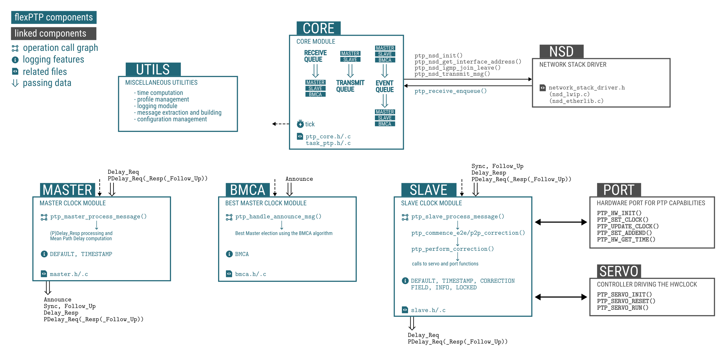
The software's inner structure is presented on the figure above. The heart of the flexPTP library is the Core module coordinating the operation of the Master and Slave blocks based on the information provided by the BMCA. All helper functions a miscellaneous utilities are summarized in the Utils block. The linked components are discussed in the External modules section.
Many Internal module feature specific logging options, to learn more refer to Events and logging.
This module is responsible for initializing the library and initiating reset procedure and propagating them to the subordinate modules. There's also a heartbeat timer (125ms period by default, see PTP_HEARTBEAT_TICKRATE_MS) defined in this module to make scheduling throughout the library possible without raising race-conditions. Also note no messaging frequency can be greater than the frequency of this clock. That's why, the default minimum log. period for all messages is -3 (see PTP_LOGPER_MIN). This module also handles the receive and transmit messaging queues and a separate event queue used for inter-module communication. The FreeRTOS task associated with the library is defined and configured by this module too.
The core module itself is not processing PTP messages, just filters and forwards them to the relevant modules. Only messages matching the current profile (Delay Mechanism, Transport Type, Domain, Transport Specific) are passed through. Messages generated and received by the specific blocks are indicated on the block diagram.
The initialize of the library start with invoking calling reg_task_ptp(). This function constructs the input, output and event queues, loads the hardware address, initializes the subordinate (BMCA (ptp_bmca_init()), Master (ptp_master_init()), Slave (ptp_slave_init())) modules, the Network Stack Driver, the Hardware Port (PTP_HW_INIT()), the Servo and finally creates the "ptp" task. The task listens for available items on any of the queues, pulls them and initiates the processing. The implementation relies on the FreeRTOS QueueSet feature.
Whenever a library reset is issued by calling ptp_reset(), the call is propagated toward all subordinate blocks (ptp_bmca_reset(), ptp_master_reset(), ptp_slave_reset()). Generally, a reset clears state machines and statistics, but does not touch the PTP profile, clock offset and priority settings.
This module contains a slightly simplified, but IEEE 1588 compatible implementation of the Best Master Clock Algorithm. The state chart is the following:
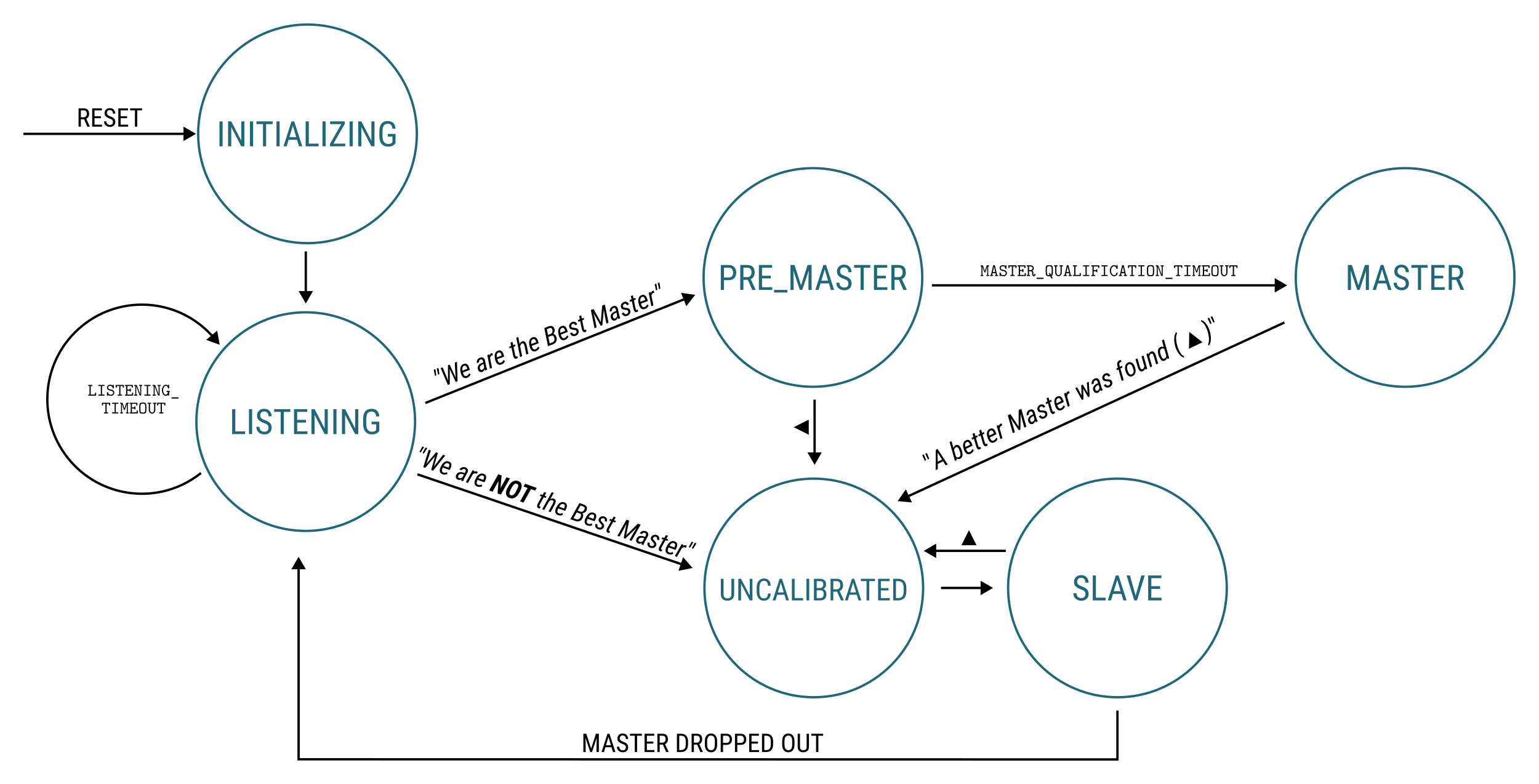
The BMCA algorithm operates based on the data in our clock's dataset (refer to Clock dataset) and based on information shipped in Announce messages. No other messaging is channeled into this module and no messages are generated by the BMCA.
Upon a BMCA state change the Core module is notified through an event to enable and disable the Master and Slave modules.
To configure BMCA parameters set BMCA macros.
This module implements the Master clock functionality. This module is enabled whenever the BMCA elects us for Best Master, i.e. the BMCA state is MASTER. The module periodically issues all Master-related PTP messages indicated in the top figure.
The Master module can be disabled in compile time using the PTP_ENABLE_MASTER_OPERATION macro if a Slave-only operation was desired.
There're a couple of runtime-settable flags also influencing the Master mode. Some profile presets also use these features.
| Flag | Value | Description |
|---|---|---|
PTP_PF_ISSUE_SYNC_FOR_COMPLIANT_SLAVE_ONLY_IN_P2P | 0x01 | Send Sync messages only for a compliant peer in P2P mode |
PTP_PF_SLAVE_ONLY | 0x02 | Operate Slave-only |
Mostly in gPTP mode, the Master clock only commences sending Sync messages if the peer has responded Master's PDelay_Req messages for a while, the Mean Path Delay to the Slave is below a specific threshold and some other criteria has been met. In flexPTP's term this concept is called "Compliant peer" and only the continuity and message frequency are checked. To learn more about this feature, refer to ptp_master_p2p_slave_reported() and ptp_master_process_message().
In P2P modes Mean Path Delay is calculated using the following formulae taken from the IEEE 1588 Standard, considering we have issued the initiating PDelay_Req:
\( \text{MPD} = \frac{(T_\text{PDelay_Resp_RX} - T_\text{PDelay_Resp_TX}) - (T_\text{PDelay_Req_TX} - T_\text{PDelay_Req_RX}) - (\text{CF}_\text{PDelay_Resp} + \text{CF}_\text{PDelay_Resp_Follow_Up})}{2}\)
\( \text{MPD} = \frac{(T_\text{PDelay_Resp_RX} - T_\text{PDelay_Req_TX}) - \text{CF}_\text{PDelay_Resp}}{2}\)
This module implements the Slave clock functionality. This module is enabled whenever the BMCA decides there're better masters on the network than us or if the Master module is completely disabled through the compile time configuration.
All messages indicated in the top figure channelled into the Slave module are processed in the ptp_slave_process_message() function, which later invokes ptp_perform_correction() to compute time error and execute the servo algorithm.
Time error is computed using the following formula, based on the IEEE 1588 Standard:
\( \Delta t = T_\text{Sync_RX} - T_\text{Sync_TX} - \text{MPD} - (\text{CF}_\text{Sync} + \text{CF}_\text{Follow_Up})\)
Mean Path Delay is calculated using the following formulae, based on the IEEE 1588 Standard:
\( \text{MPD} = \frac{T_\text{Sync_RX} - T_\text{Sync_TX} - (T_\text{Delay_Req_TX} - T_\text{Delay_Req_RX}) - (\text{CF}_\text{Sync} + \text{CF}_\text{Follow_Up} + \text{CF}_\text{Delay_Resp})}{2} \)
\( \text{MPD} = \frac{T_\text{Sync_RX} - T_\text{Sync_TX} - (T_\text{Delay_Req_TX} - T_\text{Delay_Req_RX}) - (\text{CF}_\text{Sync} + \text{CF}_\text{Delay_Resp})}{2} \)
The structure and purpose of External modules are discussed deeply in Porting and configuration.